building. climate. excellence.
More

building. climate. excellence.
building. climate. excellence.
building. climate. excellence.

CS = complete units, UC = unmixed heating circuit, MC = mixed heating circuit, F = flush mounting version, S = surface mounting version, SI = surface mounting version for a insulated case / cover, DHWC = domenstic hot water circulation, CU = cooper soldered plate heat exchanger, SX = sealed cooper soldered plate heat exchanger
2.1 Defined at a prim. flow temp. of 55°C and a DHW temperature increase of 35 K.
2.2 Defined at a prim. flow temp. of 65°C and a DHW temperature increase of 40 K.
2.3 Defined at a prim. flow temp. of 65°C and a DHW temperature increase of 35 K.
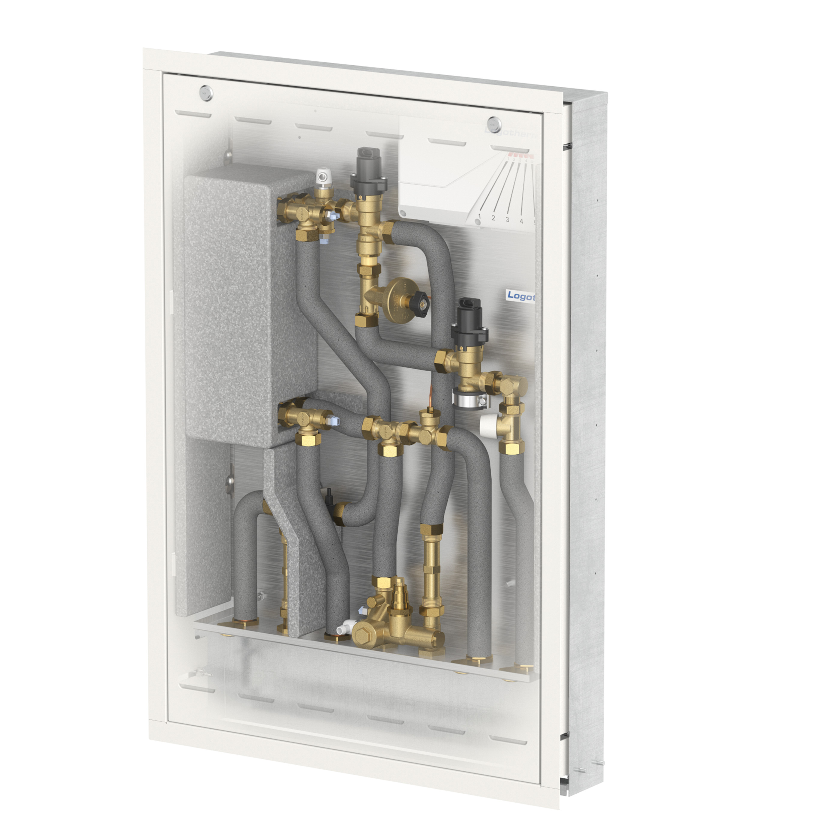
Note: all illustrations are similar to real design. It is possible that the equipment and scope of delivery may vary. The scope of delivery are defined in the product description.
 Datasheets
| Final units | Complete units | |||||
| UC | MC | MC-UC | UC | MC | MC-UC | |
| Surface mountable version: width [mm] | 500 1) | 500 1) | 500 1) | 600 | 600 | 600 |
| Surface mountable version: heights [mm] | 760 1) | 760 1) | 760 1) | 1,050 | 1,375 | 1,375 |
| Surface mountable version: depth [mm] | 115 1) | 115 1) | 115 1) | 220 | 220 | 220 |
| Flush mountable version: width [mm] | 576 1) | 576 1) | 576 1) | 610 2) | 610 2) | 610 2) |
| Flush mountable version: heights [mm] | 775 1) | 775 1) | 775 1) | 935 2) | 1.300 2) | 1.300 2) |
| Flush mountable version: depth [mm] | 110 1) | 110 1) | 110 1) | 110-160 2) | 130-210 2) | 130-210 2) |
| Connection with bottom placement | 3/4" M | 3/4" M | 3/4" M | 3/4" F | 3/4" F | 3/4" F |
| Max. pressure load: heating circuit (prim. & sec.) and sanitary | PN10 | PN10 | PN10 | PN10 | PN10 | PN10 |
| Min. differential pressure (heating primary side) | 0,03 bar | 0,03 bar | 0,03 bar | 0,03 bar | 0,03 bar | 0,03 bar |
| Max. differential pressure (heating primary side) | 2,5 bar | 2,5 bar | 2,5 bar | 2,5 bar | 2,5 bar | 2,5 bar |
| Max. temperature load: heating (prim. & sec.) and sanitary | 100 °C | 100 °C | 100°C | 100 °C | 100 °C | 100 °C |
1) Dimensions of the single HIU without case / cover. For the dimensions of the case / cover, pleasecheck the technical data of ther cases / covers.
2) Width: dimension of the front cover (cut-out dimension larger). Height: dimension of front cover (without height adjustable feets). Depth: adjustable.
| Final units | Complete units | |||||
| UC | MC | MC-UC | UC | MC | MC-UC | |
| Microprocessor controller (230V 50Hz) with displaying of the status on the unit, parameter backup, frost protection function, commissioning assistant, displaying of alarms & faults, real-time clock for high accuracy, APP-based setting option, option of displaying for all sensor values as well as control of all actuators and testing of the sensors by using the APP 1) | ✓ | ✓ | ✓ | ✓ | ✓ | ✓ |
| Preset tap domestic hot water temperature (recommendation DVGW W551) - setting range 30-60 °C 2) | ✓ | ✓ | ✓ | ✓ | ✓ | ✓ |
| Radiator heating circuit supply, unmixed heating circuit (UC) | ✓ | - | ✓ | ✓ | - | ✓ |
| Mixer circuit (MC) with injection circuit (setting range 20-65 °C) 3) and HE pump (anti blocking function) | - | ✓ | ✓ | - | ✓ | ✓ |
| Underfloor manifold with 6 circuits (3/4" M, 0.5-5 l/min, 6 bar) | Optional | Optional | Optional | - | ✓ | - |
| Underfloor manifold with 8 circuits (3/4" M, 0.5-5 l/min, 6 bar) | Optional | Optional | Optional | - | - | ✓ |
| Electrically fast and continuously adapting control valve with adaptive priority control for domenstic hot water | ✓ | ✓ | ✓ | ✓ | ✓ | ✓ |
| Directly immersed sensors for a fast reaction | ✓ | ✓ | ✓ | ✓ | ✓ | ✓ |
| Achievable low primary return temperatures during the DHW preparation based on the electronic regulation of the primary energy supply (depending on the primary conditions) | ✓ | ✓ | ✓ | ✓ | ✓ | ✓ |
| Controllable heating operation via external controller (potential-free signal of 230V as an ON / OFF function) | ✓ | ✓ | ✓ | ✓ | ✓ | ✓ |
| Controllable heating operation via external controller (0-10V as modulating controlling) | ✓ | ✓ | ✓ | ✓ | ✓ | ✓ |
| Weather compensating heating circuit controlling 3) | - | ✓ | ✓ | - | ✓ | ✓ |
| Exact quantity-based domestic hot water preparation by using a robust turbine flow sensor (1-30 l/min.) | ✓ | ✓ | ✓ | ✓ | ✓ | ✓ |
| Stainless steel plate heat exchanger, vertical positioning for reducing of risks of calcification | ✓ | ✓ | ✓ | ✓ | ✓ | ✓ |
| Control valve for heating (zone valve for connection to living space control) | ✓ | ✓ | ✓ | ✓ | ✓ | ✓ |
| Venting spots with hose connection at the primary heating side | ✓ | ✓ | ✓ | ✓ | ✓ | ✓ |
| Spool piece for a heat meter (3/4" × 110mm) and sensor pocket (M10x1) | ✓ | ✓ | ✓ | ✓ | ✓ | ✓ |
| Saving energy with pipes made of insulated corrugated stainless steel | ✓ | ✓ | ✓ | ✓ | ✓ | ✓ |
| Completely mechanically assembled on a base plate and tested | ✓ | ✓ | ✓ | ✓ | ✓ | ✓ |
| Strainer with stainless steel sieve insert (including drainage function) for high operational reliability | ✓ | ✓ | ✓ | ✓ | ✓ | ✓ |
| Second cold water connection for the apartment | ✓ | ✓ | ✓ | ✓ | ✓ | ✓ |
| Spool piece for a cold water meter (3/4" × 110mm) | ✓ | ✓ | ✓ | ✓ | ✓ | ✓ |
| Keep warm function of the primary heating water supply (not inside the measuring circuit of the heat meter) via an adjustable circulation bridge (35-65 °C) | ✓ | ✓ | ✓ | ✓ | ✓ | ✓ |
| Differential pressure control valve (range 5-25 kPa) for autom. hydr. alignment of the secondary heating circuit | ✓ | ✓ | ✓ | ✓ | ✓ | ✓ |
| Volume flow limiter for a domenstic hot water regulation 4) | ✓ | ✓ | ✓ | ✓ | ✓ | ✓ |
| 7 ball valves DN20, one with a sensor pocket for the heat meter & some of them are drinking water ball valves (DVGW tested) | Optional | Optional | Optional | ✓ | ✓ | ✓ |
| Adjustable screed heating function | - | ✓ | ✓ | - | ✓ | ✓ |
| Internal data storage with log function | ✓ | ✓ | ✓ | ✓ | ✓ | ✓ |
| Domestic hot water circulation (including insulation of the heat exchanger) with various adjustable control options (time window, DVGW compliant, etc.) 1) and data logging as well as a possible disinfection | "DHW-C" Version | "DHW-C" Version | "DHW-C" Version | - | - | - |
| Surface-mounted housing (isolated with white front cover) - version SI | Optional | Optional | Optional | SI o. F | SI o. F | SI o. F |
| Surface-mounted housing (coated steel, white) - version S | Optional | Optional | Optional | - | - | - |
| Flush-mounted housing (coated steel, white) - Version F | Optional | Optional | Optional | SI o. F | SI o. F | SI o. F |
1) Use of the Flamconnect APP and connection via Bluetooth. Check end upfront that the device is suitability.
2) Width: dimension of the front cover (cut-out dimension larger). Height: dimension of front cover (without height adjustable feets). Depth: adjustable.
3) Preset values can be changed by using the existing APP.
4) Except the L-Line version.
Flamco has been involved in the development, production and sale of high-quality components for use in HVAC systems since 1956. It is part of the stocklisted Aalberts NV, instituted in 1975. Along with Comap, which helps manage water and energy through its thermal and sanitary products that increase comfort in buildings, the Aalberts hydronic flow control business unit was constituted. Stronger together, Flamco and Comap will continue to build mission critical technologies to manage heating and cooling humanly with better financial and environmental efficacy. From source to emitter we partner with our customers to engineer seamless energy efficient hydronic systems for their building requirements.
comap.aalberts-hfc.com | aalberts-hfc.com
Stay up-to-date. Subscribe to our newsletter.
I agree to the processing of my personal data. Aalberts hydronic flow control attaches importance to your privacy.